2.6 The Title Block
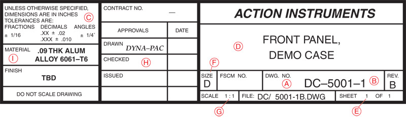
Large companies often have drafting paper or material printed in large quantities with their own specially designed title block imprinted on each sheet. Figure 2-13 shows a typical drawing title block, which contains a great deal of information that is required to make a part or an assembly.
The information given in a title block may include the following:
The information given in a title block may include the following:
a.Drawing Number. Each drawing has a unique number to identify it.
b.Dash Number. A dash followed by a number may be added to the drawing number to distinguish between right- and left-hand parts or assembly and detail drawings.
c.Permitted Part Size Tolerances. These are tolerances that define how accurately a part must be made.
d.Name Given the Part or Assembly. This is a descriptive name that describes the part or its function.
e.Sheet Number. Many sheets may be required to make all the parts required for a single assembly. If so, each page is numbered as follows: “Sheet 1 of 20,” “Sheet 2 of 20,” and so on.
f.Drawing Sheet Size. Drawings are made on a variety of sheet sizes. The assembly drawing is normally on a large sheet with detail drawing on smaller sheets. The sheet size is shown as a letter code running from A to E. An “A” sheet is about 9″×11″ and “E” is about 36″×48″.
g.Scale of the Drawing. Drawings may be made actual size, or they may be made smaller or larger than the actual size of the object. A drawing that is twice the actual size of the part would show a scale of 2 = 1 or 2:1. A drawing made half the actual size of a part would be in a scale of 1/2 = 1 or simply 1:2. The title block in Figure 2-13 shows the scale of the drawing as 1:1, meaning it is drawn to actual size.
h.Responsible Signatures Area. Spaces are often provided for signatures of the part designer, draftsperson, drawing checker, supervisor, inspector, or others involved in the production of a part.
i.Material. The material to be used in making the part is shown.

Other information may be given in a title block, depending on the company that designs and draws the part or assembly. For example, the drawing may include change orders. When requested changes have been made, the change is briefly described and a date of the change is given. Parts must be made according to the latest drawing change.
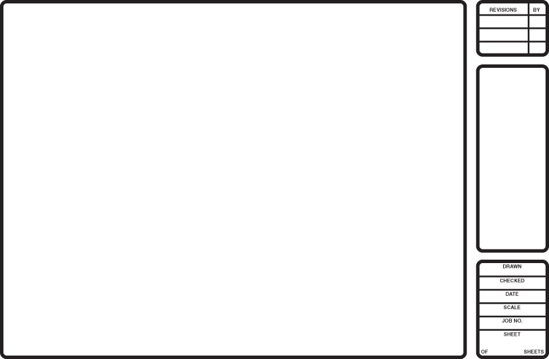
Drawings that are made on a computer are typically printed on paper that has the title block at one side, as shown in Figure 2-14.
Drawings that are made on a computer are typically printed on paper that has the title block at one side, as shown in Figure 2-14.

