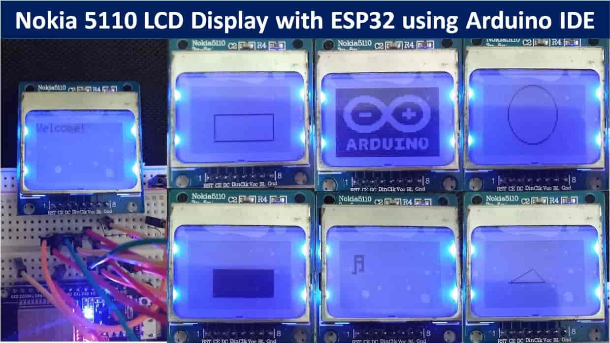
In this user guide, we will learn to interface Nokia 5110 Graphic LCD Display with ESP32 using Arduino IDE. We will discuss how to display simple texts, rotate texts, draw numbers and shapes on Nokia 5110 LCD display. Additionally, we will also display a monochrome bitmap image on the screen.
We have a similar guide with Arduino:
Nokia 5110 Graphic LCD Display
Nokia 5510 LCD display is a graphics screen LCD display and has been used for a lot of applications. Initially, it was designed only for iconic Nokia 5510 cell phone screen but now we can easily use it for different purposes such as for displaying alphanumeric characters, draw lines, shapes, and even for displaying bitmap images because of its 84X48 monochrome pixels that mean 84 columns and 48 rows. All necessary functions of this display are packed in a single small chip which is operated at very low voltages. It is very cost effective, more precise, more reliable and easy to use than LCD display.

Recommended Reading: Nokia5110 LCD Module
Nokia5110 Pinout Diagram
The pin configuration of the LCD is almost SPI but in one-way only. The LCD only uses a one-way communication to operate because it doesn’t have to send any data to the microcontroller. However, it has two modes of data and command modes for operating properly.
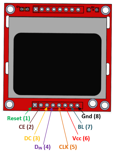
The table below shows the eight pins found on the Nokia 5510 LCD Display. You can also view their descriptions.
| Pin | Description |
| Pin6: Power (VCC) | The power pin will power up the LCD with external voltage to activate it. |
| Pin7: Back Light (BL) | The backlight is the internal colour of the LCD. It will turn ON by giving the power input to its pin. |
| Pin8: Ground (GND) | The ground is internally common with LED and whole LCD. It helps to make common ground with external power and devices. |
| Pin1: Reset | The reset pins are to reset the Nokia5110 display. Here it will help in the programming library to reset it. |
Pin2: Chip Enable (CE) | The enable pin in SPI helps to select the device in case of multiple devices. Here it will active the LCD with the LOW input signal. |
| Pin3: Data/Command (DC) | Pin3 helps to switch between the command/data mode. The HIGH signal is for data and LOW signal for command. |
| Pin4: Serial IN (DIN) | The “Serial In” pin will send the data from the microcontroller to the LCD Nokia5110. |
Pin5: Clock (CLK) | The LCD and microcontroller will require a common clock to operate because of their SPI communication. CLK pin will help to make it. |
Descriptions of Pins
Every Nokia 5510 LCD display consists of eight pins which are used for different purposes.
- The first pin is the reset pin and used for resetting the LCD display. During reset zero voltages are applied at this pin.
- Second pin is the CE pin, which is enable pin and is used for displaying any particular display when more then one SPI peripherals are in used.
- Third pin is the DC pin, which data/command pin and is used for switching data mode (high) to command mode (low).
- Fourth pin is the DIN pin, which serial input pin and is used for serial communication means for sending serial instruction or data.
- Fifth pin is the CLK pin, which is clock pin and is used for suppling clock source because all SPI modules are required a common clock.
- Sixth pin is the VCC pin, which is voltage supplying pin and is used for turning the LCD display ON or OFF. This LCD display requires 2.7V-3.3V DC voltage to power it up.
- Seventh pin is the BL pin, which is the back light pin and used for powering on the back light of this LCD display.
- Similarly, the eighth pin is the GND pin, which is the ground pin and is used for supplying ground voltages to this LCD display.
Pins 1-5 are used for SPI communication whereas Pins 6-8 are for powering the display and enabling the back light.
Interfacing Nokia 5510 with ESP32 board
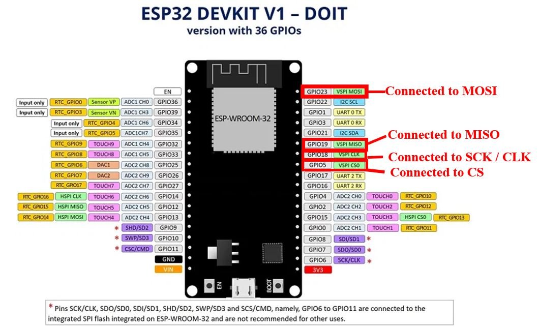
As we have seen above, the Nokia 5510 LCD display has 8 terminals which we will connect with the ESP32 board. As the OLED display requires an operating voltage in the range of 2.7-3.3V hence the VCC terminal of the LCD display will in common with the 3.3V pin of the ESP32 board. Likewise, both the devices will have their grounds in common. The SPI communication helps to communicate with LCD, which is common in every microcontroller. Thus, we will use the SPI interface of ESP32. We can either use VSPI or HSPI pins. We are using the VSPI pins in this case. Below you can view the VSPI pins in the ESP32 module. We will be using the MOSI, CLK and the CS pins from this interface. For RST and DC, you can use any appropriate ESP32 pin.
The table below shows the connections between the two devices that we will use in our project.
| Nokia 5510 LCD Display | ESP32 board |
| Pin1 (RST) | GPIO2 |
| Pin2 (CE) | GPIO15 |
| Pin3 (DC) | GPIO4 |
| Pin4 (Din) | GPIO23 |
| Pin5 (Clk) | GPIO18 |
| Pin6 (Vcc) | 3.3V |
| Pin7 (BL) | 3.3V via 220 ohm limiting resistor |
| Pin8 (GND) | GND |
As we want to turn the back light ON for this project, hence we are connecting the BL pin with 3.3V from ESP32 through a 220 ohm limiting resistor. This will keep the back light ON. You can use another configuration for BL as well.
Components Required
We will need the following components to connect our ESP32 board with the Nokia 5510 Display.
- ESP32 board
- Nokia 5510 LCD Display
- 220 ohm resistor
- Connecting Wires
- Breadboard
Schematic ESP32 with Nokia 5510 Display
Follow the schematic diagram below for the ESP32 module and connect them accordingly.
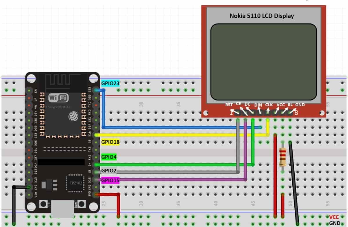
All the connections between the two devices are the same as we listed them in the table above.
Installing Nokia 5510 Library in Arduino IDE
We will use Arduino IDE to program our ESP32 development board. Thus, you should have the latest version of Arduino IDE. Additionally, you also need to install the ESP32 plugin.
If your IDE does not have the plugin installed you can visit the link below: Installing ESP32 library in Arduino IDE and upload code.
To use the Nokia 5510 display in our project, we have to install the Adafruit Nokia 5510 library and the Adafruit GFX library in Arduino IDE. Follow the steps below to successfully install them.
Open Arduino IDE and click on Sketch > Library > Manage Libraries
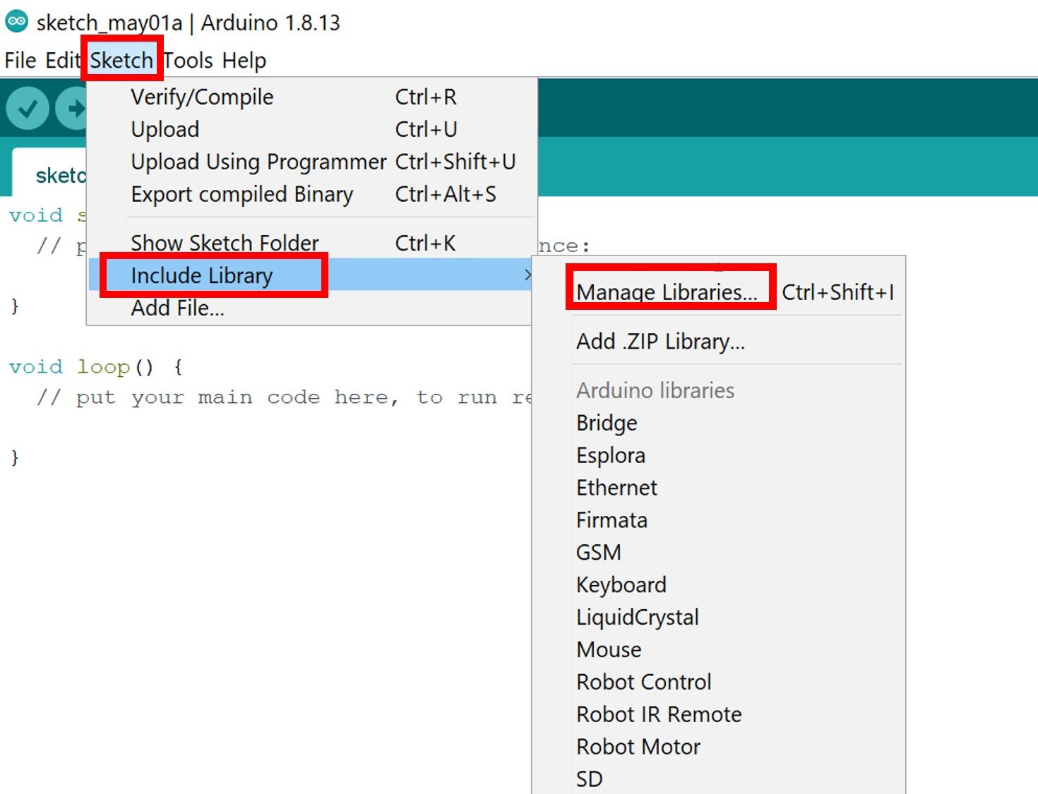
The following window will open up.

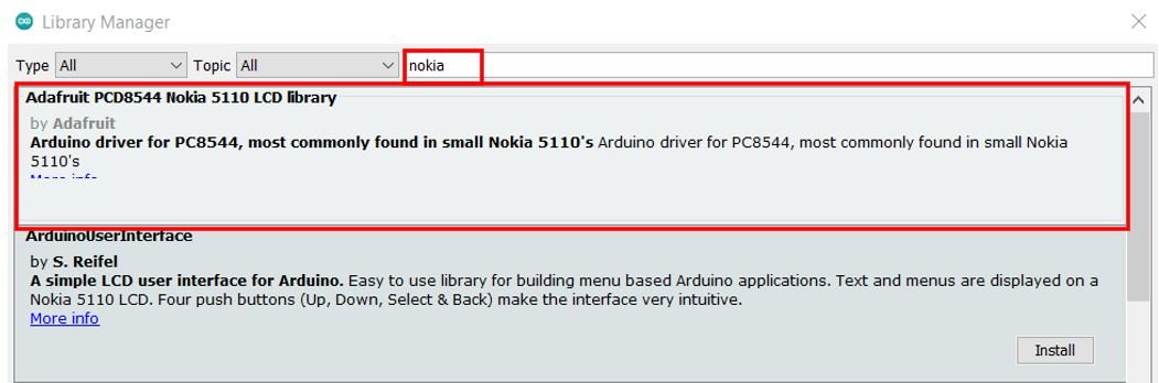
Type ‘nokia’ in the search tab and install the Adafruit Nokia 5510 LCD library
We will also require the Adafruit GFX library which is needed to display different shapes. Type ‘Adafruit GFX’ in the search tab and install it as well.
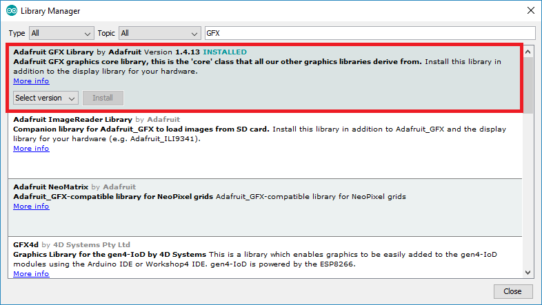
After installing the libraries, restart your IDE.
Arduino Sketch: Displaying Simple Text on Nokia 5510 LCD Display
Now we will proceed further and learn how to display simple text on the Nokia 5510 LCD display. We will be using the Adafruit Nokia 5510 library to access useful functions to show you how to display texts easily on the LCD.
Open your Arduino IDE and go to File > New to open a new file. Copy the code given below in that file.
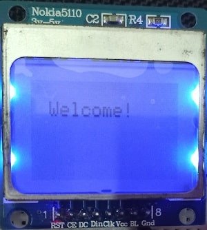
This sketch will display ‘Welcome!’ on the LCD display.
#include <SPI.h>
#include <Adafruit_GFX.h>
#include <Adafruit_PCD8544.h>

Adafruit_PCD8544 display = Adafruit_PCD8544(18,23,4,15,2);

void setup()   {
  Serial.begin(115200);
  display.begin();
  display.setContrast(50);

  display.clearDisplay();
  display.setTextSize(1);
  display.setTextColor(BLACK);
  display.setCursor(10,10);
  display.println("Welcome!");
  display.display();
}
void loop(){

}
How the Code Works?
Now let us understand how each part of the code works.
Including Libraries
Firstly, we will include all the following libraries which are required for this project. SPI.h will allow us to communicate through the SPI protocol. Whereas the other libraries are the ones which we previously installed and are required for the proper functionality of the Nokia 5510 LCD display.
#include <SPI.h>
#include <Adafruit_GFX.h>
#include <Adafruit_PCD8544.h>
Defining LCD Display
Next, we will initialize the display by creating an object of Adafruit_PCD8544 and specifying the ESP32 GPIO pins which we have connected to the Nokia 5510’s CLK, DIN, DC and RST pins respectively. In total it takes in 5 parameters. In our case, the CLK is connected with GPIO18, the DIN is connected with GPIO23, the DC is connected with GPIO4, the CE is connected with GPIO15 and the RST is connected with GPIO2. Carefully, specify the parameters.
Adafruit_PCD8544 display = Adafruit_PCD8544(18,23,4,15,2);setup() function
Inside the setup() function, we will open a serial connection at a baud rate of 115200. Moreover, we will also initialize the LCD display by using display.begin().
Serial.begin(115200);
display.begin();
Next, we will use setContrast() method on the Adafruit object. This will be used to set the contrast of the display for a better view of the text on the screen. It takes in values between 0-100 but values from 50-60 give a good result. You can change the values and see what suits you better. We have set it to 50.
display.setContrast(50);Displaying Text on LCD
To show the text on the LCD the following commands will help. In the text display command the fonts, size, and types are changeable.
First, we will clear the buffer by using clearDisplay() on the Adafruit object.
display.clearDisplay();Then to set the size of the text, we will use setTextSize() and pass the size as a parameter inside it. 1 denotes the smallest size and it increases relatively after incrementing it. We have set the font size as default which is 1.
display.setTextSize(1);Next, we will control the color of the text by using the setTextColor() function and passing BLACK as an argument. If we have a dark background, we will display our text in white and if we have a bright background then we will display the text in black.
display.setTextColor(BLACK);We will use the setCursor() function to denote the x and the y axis position from where the text should start. We have passed (10,10) as the parameter. The first parameter is the x-axis position that (+x) increases towards the right. The second parameter is the y-axis position that (+y) increases downwards.
display.setCursor(10,10);Then by using println() we will pass the text which we want to display on the OLED. It is ‘Welcome!’ in our case. You can display any message. Just specify it like you do when printing strings/variables of serial objects.
display.println("Welcome!");Finally, we will call the display() function on the display object so that the text displays on the LCD screen.
display.display();Demonstration
Choose the correct board and COM port before uploading your code to the ESP32 board. Go to Tools > Board and select ESP32 Dev Module.

Next, go to Tools > Port and select the appropriate port through which your board is connected.

Now click on the upload button to upload code to ESP32. After that press the enable button on ESP32.

The LCD Display will start displaying the text on its screen. You can have a look at it in the picture given below.
Arduino Sketch: Displaying Various Texts
Open your Arduino IDE and go to File > New to open a new file. Copy the code given below in that file.
This sketch will display all the listed illustrations after a delay of 10 seconds.
- Inverting Text colours (Dark/Bright)
- Scaling Font Size
- Display numbers
- Showing Base for numbers
- ASCII Symbols
- Rotate Text
#include <SPI.h>
#include <Adafruit_GFX.h>
#include <Adafruit_PCD8544.h>

Adafruit_PCD8544 display = Adafruit_PCD8544(18,23,4,15,2);

int rotate = 1;

void setup()   {
  Serial.begin(115200);
  display.begin();
  display.setContrast(50);
  display.clearDisplay();
  display.setTextSize(1);
  display.setTextColor(BLACK);
  display.setCursor(10,10);
  display.println("Welcome!");
  display.display();
  delay(10000);
  display.clearDisplay();

  display.setTextColor(WHITE, BLACK); //inverting Text colour
  display.setCursor(10,10);
  display.println("Welcome!");
  display.display();
  delay(10000);
  display.clearDisplay();

  display.setTextColor(BLACK);  //scaling font size
  display.setCursor(0,10);
  display.setTextSize(2);
  display.println("Welcome!");
  display.display();
  delay(10000);
  display.clearDisplay();


  display.setTextSize(1);   //display numbers
  display.setCursor(10,10);
  display.println(12345);
  display.display();
  delay(10000);
  display.clearDisplay();


  display.setCursor(0,0);  //showing base
  display.print("0x"); display.print(0xFF, HEX);
  display.print("(HEX) = ");
  display.print(0xFF, DEC);
  display.println("(DEC)");
  display.display();
  delay(10000);
  display.clearDisplay();


  display.setCursor(10,10);  //ASCII symbol
  display.setTextSize(2);
  display.write(14);
  display.display();
  delay(10000);
  display.clearDisplay();


  while(1)
  {
  display.clearDisplay();
  display.setRotation(rotate);
  display.setTextSize(1);
  display.setTextColor(BLACK);
  display.setCursor(0,0);
  display.println("Welcome!");
  display.display();
  delay(1000);
  display.clearDisplay();
  rotate++;
  }
}

void loop() {}
How the Code Works?
In this part, we will show you how to display the different texts. Inside the void setup() function, after setting the serial baud rate and clearing the buffer we will include the code to display the simple text then invert its background colour, numbers, ASCII symbol and text rotation. Each illustration will display on the LCD screen for 10 seconds and then the next one follows. The rotating text will continue in an infinite loop after all previous illustrations have been shown.
Before displaying each shape we will call the clearDisplay() function to clear the buffer for the next illustration.
Inverting Text Colour
After displaying the simple text ‘Welcome!’ on the LCD screen as we did in the previous sketch, we will invert its background colour. This is achieved by using the setTextColor() function on the Adafruit_PCD8544 object that is ‘display.’ This function takes in two parameters. The first parameter is the font colour and the second parameter is the background colour. We have set the font colour as WHITE and the background colour as BLACK. This is opposite to what we had before. Additionally, we will call the display() function on the display object so that the inversion displays on the LCD.
 display.setTextColor(WHITE, BLACK); //inverting Text colour
  display.setCursor(10,10);
  display.println("Welcome!");
  display.display();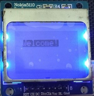
Scaling Font Size
Next, we will change the font size. First we will change the text colour back to Black. Next by using setTextSize() function and pass the font size as a parameter inside it. In our case it is 2 that relatively increases the font size as compared to 1. Remember this function takes in positive values where 1 is the smallest size. The text is scaled by 5:7 where font size 2 means 10×14 pixels enhancement. Additionally, we will call the display() function on the display object so that the font size displays on the LCD.
display.setTextColor(BLACK);  //scaling font size
  display.setCursor(0,10);
  display.setTextSize(2);
  display.println("Welcome!");
  display.display();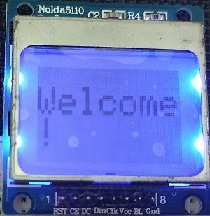
Displaying Numbers
Now, we will show you how to display numbers on the LCD screen. Just set your text size and cursor position. Then by using the println() function pass the numbers that you want to display on the screen. In our case we are displaying ‘12345’. Additionally, we will call the display() function on the display object so that the numbers display on the LCD.
display.setTextSize(1);   //display numbers
  display.setCursor(10,10);
  display.println(12345);
  display.display();
Showing Base for Numbers
Now we will show the base for a number on our LCD display. We will convert a hexadecimal number to decimal format and display it on the LCD. The number is 255 in decimal and 0xFF in hexadecimal. The print() will take in two parameters to achieve this. The first is the number and the second is the base format (HEX/DEC) in our case. Additionally, we will call the display() function on the display object so that the numbers display on the LCD.
display.setCursor(0,0);  //showing base
  display.print("0x"); display.print(0xFF, HEX);
  display.print("(HEX) = ");
  display.print(0xFF, DEC);
  display.println("(DEC)");
  display.display();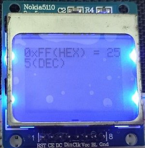
Displaying ASCII symbol
Now let us learn how to display an ASCII symbol. First set up the font size and the cursor position. We have set the font size to 2 and the cursor at (10,10). This will give us a good view of the symbol. Now by using the write() function on the Adafruit_PCD8544 object that is ‘display’ we will pass a number inside it. This will send the binary data and display it on the screen by converting it to ASCII text. We are passing 14 inside it which denotes the ASCII symbol for musical note. Additionally, we will call the display() function on the display object so that the symbol displays on the LCD.
display.setCursor(10,10);  //ASCII symbol
  display.setTextSize(2);
  display.write(14);
  display.display();
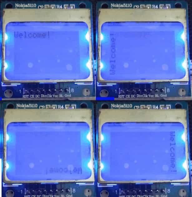
Rotating Text
Lastly, we will rotate the ‘Welcome!’ text in all directions on the LCD screen. This will be achieved by using the setRotation() function that takes in values from 0-3 where 0 denotes rotation of 0 degrees, 1 denotes rotation of 90 degrees, 2 denotes rotation of 180 degrees and 3 denotes a rotation of 270 degrees. We initially defined an integer variable named ‘rotation’ and set it equal to 1. Inside the infinite loop() we will rotate the text 90 degrees as the rotate variable increments after each rotation. There is a delay of 1 second between each rotation.
while(1)
  {
  display.clearDisplay();
  display.setRotation(rotate);
  display.setTextSize(1);
  display.setTextColor(BLACK);
  display.setCursor(0,0);
  display.println("Welcome!");
  display.display();
  delay(1000);
  display.clearDisplay();
  rotate++;
  }
Demonstration
To see the demonstration of the above code, upload the code to Arduino. Before uploading the code, make sure to select the ESP32 board from Tools > Board. Also, select the correct COM port to which the ESP32 board is connected from Tools > Port.
Once the code is uploaded to ESP32, you will be able to view all the above mentioned illustrations on the LCD display after a gap of 10 seconds. Watch the video below to have a look.
Arduino Sketch: Displaying Simple Shapes
Now let us move ahead and learn how to display different shapes on the Nokia 5110 LCD display. By the end of this section you will be able to display the following shapes on your LCD screen:
- Rectangle (Unfilled and Filled)
- Rounded Rectangle (Unfilled and Filled)
- Circle (Unfilled and Filled)
- Triangle (Unfilled and Filled)
Open your Arduino IDE and go to File > New to open a new file. Copy the code given below in that file.
This sketch will display all the above listed shapes after a delay of 5 seconds.
#include <SPI.h>
#include <Adafruit_GFX.h>
#include <Adafruit_PCD8544.h>

Adafruit_PCD8544 display = Adafruit_PCD8544(18,23,4,15,2);

void setup()   {
  Serial.begin(115200);
  display.begin();
  display.setContrast(50);
  display.clearDisplay();

  display.drawRect(20, 20, 50, 20, BLACK);
  display.display();
  delay(5000);
  display.clearDisplay();

  display.fillRect(20, 20, 50, 20, BLACK);
  display.display();
  delay(5000);
  display.clearDisplay();

  display.drawRoundRect(20, 20, 50, 20, 10, BLACK);
  display.display();
  delay(5000);
  display.clearDisplay();

  display.fillRoundRect(20, 20, 50, 20, 10, BLACK);
  display.display();
  delay(5000);
  display.clearDisplay();

  display.drawCircle(40, 20, 20, BLACK);
  display.display();
  delay(5000);
  display.clearDisplay();

  display.fillCircle(40, 20, 20, BLACK);
  display.display();
  delay(5000);
  display.clearDisplay();

  display.drawTriangle(40, 20, 20, 30, 50, 30, BLACK);
  display.display();
  delay(5000);
  display.clearDisplay();

  display.fillTriangle(40, 20, 20, 30, 50, 30, BLACK);
  display.display();
  delay(5000);
  display.clearDisplay();
}

void loop() {}
How the Code Works?
In this part, we will show you how to display the different simple shapes. Inside the void setup() function, after setting the serial baud rate and clearing the buffer we will include the code to display the shapes. Each illustration will display on the LCD screen for 5 seconds and then the next one will follow.
Before displaying each shape we will call the clearDisplay() function to clear the buffer for the next illustration.
Draw Rectangle (Unfilled and Filled)
First, we will display a series of different rectangles on the LCD screen that include an unfilled and a filled rectangle. First, we will display an unfilled rectangle. This is achieved by using the drawRect() function on the Adafruit_PCD8544 object that is ‘display.’ This function takes in five parameters. The first two parameters are the starting (x1, y1) coordinates that indicate the top left corner of the rectangle. The next two parameters are the width and height of the rectangle. Lastly the fifth parameter is the colour of the rectangle. We have passed (20,20) as the starting coordinates and 50 as the width and 20 as the height of the rectangle. It will be black in colour. Additionally, we will call the display() function on the display object so that the rectangle displays on the screen.
display.drawRect(20, 20, 50, 20, BLACK);
  display.display();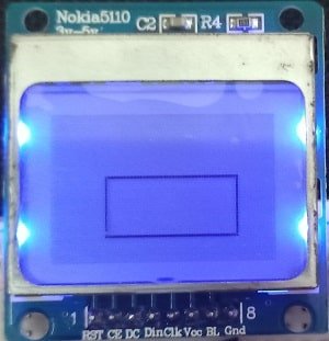
Next, we will display a filled rectangle. This is achieved by using the fillRect() function. This function takes in the same five parameters.
display.fillRect(20, 20, 50, 20, BLACK);
  display.display();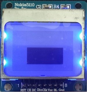
Draw Rounded Rectangle (Unfilled and Filled)
Additionally, we will also display a rounded rectangle. This is achieved by using the drawRoundRect() function. This function takes in six parameters. The first two parameters are the starting (x1, y1) coordinates that indicate the top left corner of the rectangle. The next two parameters are the width and height of the rectangle. The fifth parameter is the radius of the corner. We have passed (20,20) as the starting coordinates and 50 as the width and 20 as the height of the rectangle. For the radius of the corners we have set it to 10. The rectangle will be black in colour. Additionally, we will call the display() function on the display object so that the rounded rectangle displays on the LCD.
display.drawRoundRect(20, 20, 50, 20, 10, BLACK);
  display.display();
Moreover, we can also display a filled rounded rectangle by using fillRoundRect() function. The rest of the parameters remain the same.
display.fillRoundRect(20, 20, 50, 20, 10, BLACK);
  display.display();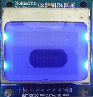
Displaying Circle (Unfilled and Filled)
Now, we will display a circle. This is achieved by using the drawCircle() function. This function takes in four parameters. The first two parameters are the (x, y) coordinates that indicate the center of the circle. The next parameter is the radius of the circle. The last parameter is the color of the circle. We have passed (40,20) as the center coordinates of the circle and the radius as 20. The circle will be black in color. Additionally, we will call the display() function on the display object so that the circle displays on the LCD.
display.drawCircle(40, 20, 20, BLACK);
  display.display();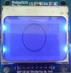
To display a filled circle we will use the fillCircle() function. The rest of the parameters remain the same.
display.fillCircle(40, 20, 20, BLACK);
  display.display();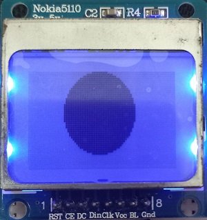
Drawing a Triangle (Unfilled and Filled)
To display a triangle we will use the drawTriangle() function. This function takes in seven parameters. The first two parameters are the (x1, y1) coordinates of the first corner of the triangle. The next two parameters are the (x2, y2) coordinates of the second corner of the triangle. Likewise the fifth and sixth parameters are the (x3, y3) coordinates of the third corner of the triangle. The last parameter is the colour of the triangle. We have passed (40,20) as the first corner, (20, 30) as the second corner and (50, 30) as the third corner of the triangle. The triangle will be black in colour. Additionally, we will call the display() function on the display object so that the triangle displays on the LCD screen.
display.drawTriangle(40, 20, 20, 30, 50, 30, BLACK);
  display.display();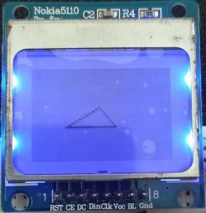
To display a filled triangle we will use the fillTriangle() function. The rest of the parameters will remain the same.
display.fillTriangle(40, 20, 20, 30, 50, 30, BLACK);
  display.display();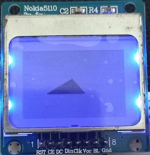
Demonstration
To see the demonstration of the above code, upload the code to Arduino. Before uploading the code, make sure to select the ESP32 board from Tools > Board. Also select the correct COM port to which the ESP32 board is connected from Tools > Port.
Once the code is uploaded to ESP32, you will be able to view all the above mentioned figures on the OLED display after a gap of 5 seconds. Watch the video below to have a look.
Displaying Bitmap Images on Nokia 5110 LCD Display with ESP32
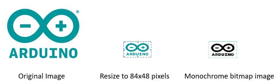
Now let us look at something more interesting to display on our graphic LCD screen. We can display 84×48 (pixels) monochrome bitmap images on our screen very easily by following a couple of steps. We will just need a 84×48 .bmp image and the image array that we will obtain through an image to array converter. The rest of the steps we have already seen in the examples above.
First, we will need an image of size 84×48 in pixels. We will use MS Paint to resize our image and save it in .bmp format. Below is the image that we will use.
Next, we will go to an online image to array converter called ‘image2cpp.’ Click here to go the application. The following page appears. There are four sections: Select Image, Image Settings, Preview and Output.
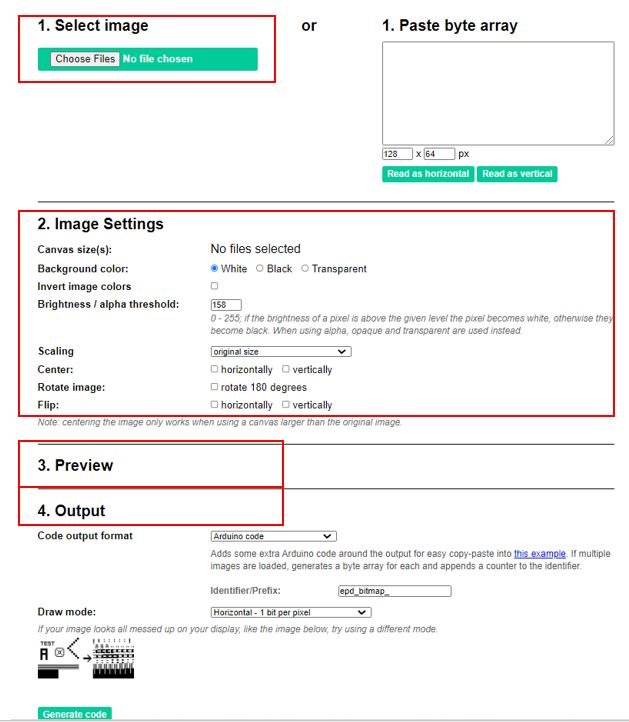
In the select image option click ‘Choose Files’ and select the .bmp file that we saved previously. We have named it as bitmap_image.bmp.

Now move ahead to the image settings. Set the canvas size to 84×48 and change the brightness according to your needs. You can view in the preview section how the bitmap image looks like. This is how it will get displayed on the LCD screen. Thus, set the brightness appropriately.
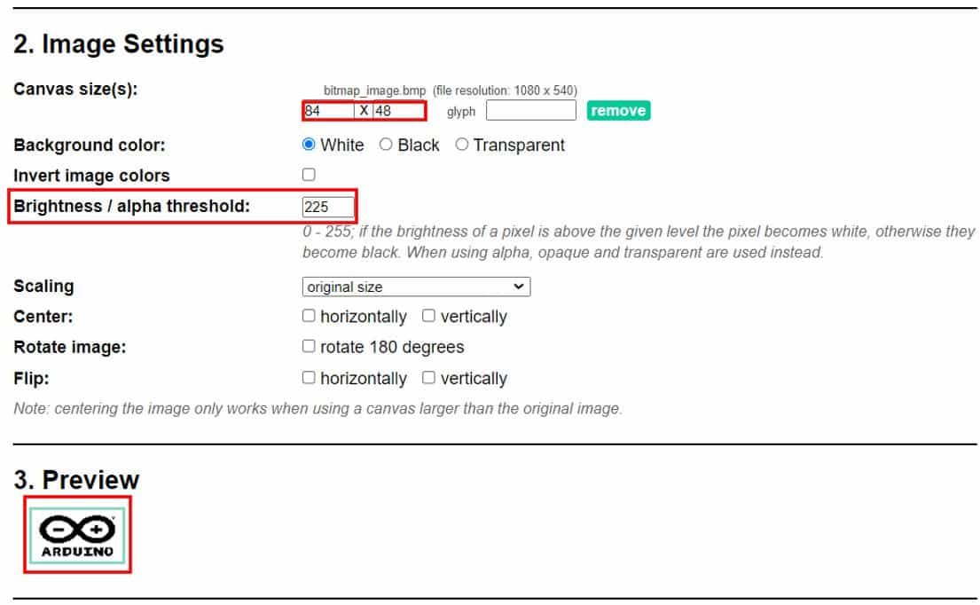
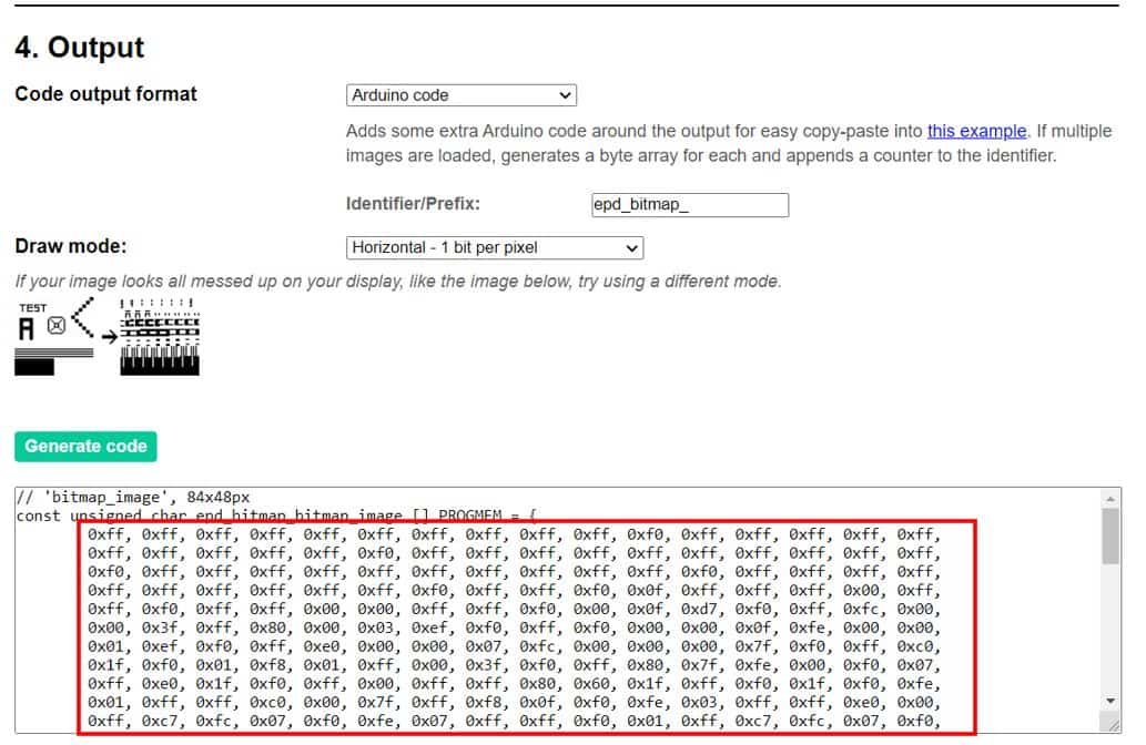
When you are satisfied with your preview then go to output and click ‘Generate code.’ Now we will obtain the array. Copy that array and save it. We will use it while programming our ESP32 board with the Nokia 5110 LCD display.
Arduino Sketch
Open your Arduino IDE and go to File > New to open a new file. Copy the code given below in that file.
This sketch will display the monochrome bitmap image on the LCD display.
#include <SPI.h>
#include <Adafruit_GFX.h>
#include <Adafruit_PCD8544.h>

Adafruit_PCD8544 display = Adafruit_PCD8544(18,23,4,15,2);

static const uint8_t bitmap_image[1024]  = {
  0xff, 0xff, 0xff, 0xff, 0xff, 0xff, 0xff, 0xff, 0xff, 0xff, 0xf0, 0xff, 0xff, 0xff, 0xff, 0xff,
  0xff, 0xff, 0xff, 0xff, 0xff, 0xf0, 0xff, 0xff, 0xff, 0xff, 0xff, 0xff, 0xff, 0xff, 0xff, 0xff,
  0xf0, 0xff, 0xff, 0xff, 0xff, 0xff, 0xff, 0xff, 0xff, 0xff, 0xff, 0xf0, 0xff, 0xff, 0xff, 0xff,
  0xff, 0xff, 0xff, 0xff, 0xff, 0xff, 0xf0, 0xff, 0xff, 0xf0, 0x0f, 0xff, 0xff, 0xff, 0x00, 0xff,
  0xff, 0xf0, 0xff, 0xff, 0x00, 0x00, 0xff, 0xff, 0xf0, 0x00, 0x0f, 0xd7, 0xf0, 0xff, 0xfc, 0x00,
  0x00, 0x3f, 0xff, 0x80, 0x00, 0x03, 0xef, 0xf0, 0xff, 0xf0, 0x00, 0x00, 0x0f, 0xfe, 0x00, 0x00,
  0x01, 0xef, 0xf0, 0xff, 0xe0, 0x00, 0x00, 0x07, 0xfc, 0x00, 0x00, 0x00, 0x7f, 0xf0, 0xff, 0xc0,
  0x1f, 0xf0, 0x01, 0xf8, 0x01, 0xff, 0x00, 0x3f, 0xf0, 0xff, 0x80, 0x7f, 0xfe, 0x00, 0xf0, 0x07,
  0xff, 0xe0, 0x1f, 0xf0, 0xff, 0x00, 0xff, 0xff, 0x80, 0x60, 0x1f, 0xff, 0xf0, 0x1f, 0xf0, 0xfe,
  0x01, 0xff, 0xff, 0xc0, 0x00, 0x7f, 0xff, 0xf8, 0x0f, 0xf0, 0xfe, 0x03, 0xff, 0xff, 0xe0, 0x00,
  0xff, 0xc7, 0xfc, 0x07, 0xf0, 0xfe, 0x07, 0xff, 0xff, 0xf0, 0x01, 0xff, 0xc7, 0xfc, 0x07, 0xf0,
  0xfc, 0x07, 0xff, 0xff, 0xf8, 0x01, 0xff, 0xc7, 0xfe, 0x07, 0xf0, 0xfc, 0x0f, 0xe0, 0x07, 0xfc,
  0x03, 0xfc, 0x00, 0x7e, 0x07, 0xf0, 0xfc, 0x0f, 0xe0, 0x07, 0xfc, 0x07, 0xfc, 0x00, 0x7e, 0x07,
  0xf0, 0xfc, 0x07, 0xe0, 0x07, 0xf8, 0x03, 0xfc, 0x00, 0x7e, 0x07, 0xf0, 0xfc, 0x07, 0xff, 0xff,
  0xf8, 0x01, 0xff, 0xc7, 0xfe, 0x07, 0xf0, 0xfe, 0x07, 0xff, 0xff, 0xf0, 0x00, 0xff, 0xc7, 0xfc,
  0x07, 0xf0, 0xfe, 0x03, 0xff, 0xff, 0xe0, 0x00, 0x7f, 0xff, 0xf8, 0x0f, 0xf0, 0xff, 0x01, 0xff,
  0xff, 0x80, 0x40, 0x3f, 0xff, 0xf0, 0x0f, 0xf0, 0xff, 0x80, 0xff, 0xfe, 0x00, 0xf0, 0x0f, 0xff,
  0xe0, 0x1f, 0xf0, 0xff, 0x80, 0x1f, 0xf8, 0x01, 0xf8, 0x01, 0xff, 0x80, 0x3f, 0xf0, 0xff, 0xc0,
  0x00, 0x00, 0x03, 0xfc, 0x00, 0x00, 0x00, 0x7f, 0xf0, 0xff, 0xf0, 0x00, 0x00, 0x0f, 0xfe, 0x00,
  0x00, 0x00, 0xff, 0xf0, 0xff, 0xf8, 0x00, 0x00, 0x1f, 0xff, 0x80, 0x00, 0x03, 0xff, 0xf0, 0xff,
  0xff, 0x00, 0x00, 0xff, 0xff, 0xe0, 0x00, 0x0f, 0xff, 0xf0, 0xff, 0xff, 0xc0, 0x07, 0xff, 0xff,
  0xfc, 0x00, 0x7f, 0xff, 0xf0, 0xff, 0xff, 0xff, 0xff, 0xff, 0xff, 0xff, 0xff, 0xff, 0xff, 0xf0,
  0xff, 0xff, 0xff, 0xff, 0xff, 0xff, 0xff, 0xff, 0xff, 0xff, 0xf0, 0xff, 0xff, 0xff, 0xff, 0xff,
  0xff, 0xff, 0xff, 0xff, 0xff, 0xf0, 0xff, 0xff, 0xff, 0xff, 0xff, 0xff, 0xff, 0xff, 0xff, 0xff,
  0xf0, 0xff, 0xe3, 0xe0, 0x70, 0x1c, 0x63, 0x00, 0x8e, 0x30, 0x3f, 0xf0, 0xff, 0xe1, 0xe0, 0x30,
  0x0c, 0x63, 0x01, 0x86, 0x33, 0x1f, 0xf0, 0xff, 0xc9, 0xe7, 0x31, 0xcc, 0x63, 0xc7, 0x82, 0x23,
  0x9f, 0xf0, 0xff, 0xc8, 0xe6, 0x31, 0xcc, 0x63, 0xc7, 0x80, 0x23, 0x9f, 0xf0, 0xff, 0x80, 0xe0,
  0x71, 0xcc, 0x63, 0xc7, 0x88, 0x23, 0x9f, 0xf0, 0xff, 0x80, 0xe6, 0x71, 0x8c, 0x63, 0xc7, 0x88,
  0x23, 0x1f, 0xf0, 0xff, 0x9c, 0x66, 0x30, 0x1c, 0x07, 0x00, 0x8c, 0x30, 0x3f, 0xf0, 0xff, 0x1e,
  0x67, 0x30, 0x7f, 0x0f, 0x00, 0xce, 0x38, 0x7f, 0xf0, 0xff, 0xff, 0xff, 0xff, 0xff, 0xff, 0xff,
  0xff, 0xff, 0xff, 0xf0, 0xff, 0xff, 0xff, 0xff, 0xff, 0xff, 0xff, 0xff, 0xff, 0xff, 0xf0, 0xff,
  0xff, 0xff, 0xff, 0xff, 0xff, 0xff, 0xff, 0xff, 0xff, 0xf0, 0xff, 0xff, 0xff, 0xff, 0xff, 0xff,
  0xff, 0xff, 0xff, 0xff, 0xf0, 0xff, 0xff, 0xff, 0xff, 0xff, 0xff, 0xff, 0xff, 0xff, 0xff, 0xf0
};

void setup()   {
  Serial.begin(115200);
  display.begin();
  display.setContrast(50);
  display.clearDisplay();
  display.drawBitmap(0, 0, bitmap_image, 84, 48, 1);
  display.display();
}

void loop() {}
How the Code Works?
This part shows how to include the image array and display the bitmap image on the LCD screen.
After including the necessary libraries and defining the Nokia LCD display we will define the image array which we got from the image2cpp application as follows. Define it as ‘static const uint8_t NAME_OF_.bmp_FILE[1024].’
static const uint8_t bitmap_image[1024]  = {
  0xff, 0xff, 0xff, 0xff, 0xff, 0xff, 0xff, 0xff, 0xff, 0xff, 0xf0, 0xff, 0xff, 0xff, 0xff, 0xff,
  0xff, 0xff, 0xff, 0xff, 0xff, 0xf0, 0xff, 0xff, 0xff, 0xff, 0xff, 0xff, 0xff, 0xff, 0xff, 0xff,
  0xf0, 0xff, 0xff, 0xff, 0xff, 0xff, 0xff, 0xff, 0xff, 0xff, 0xff, 0xf0, 0xff, 0xff, 0xff, 0xff,
  0xff, 0xff, 0xff, 0xff, 0xff, 0xff, 0xf0, 0xff, 0xff, 0xf0, 0x0f, 0xff, 0xff, 0xff, 0x00, 0xff,
  0xff, 0xf0, 0xff, 0xff, 0x00, 0x00, 0xff, 0xff, 0xf0, 0x00, 0x0f, 0xd7, 0xf0, 0xff, 0xfc, 0x00,
  0x00, 0x3f, 0xff, 0x80, 0x00, 0x03, 0xef, 0xf0, 0xff, 0xf0, 0x00, 0x00, 0x0f, 0xfe, 0x00, 0x00,
  0x01, 0xef, 0xf0, 0xff, 0xe0, 0x00, 0x00, 0x07, 0xfc, 0x00, 0x00, 0x00, 0x7f, 0xf0, 0xff, 0xc0,
  0x1f, 0xf0, 0x01, 0xf8, 0x01, 0xff, 0x00, 0x3f, 0xf0, 0xff, 0x80, 0x7f, 0xfe, 0x00, 0xf0, 0x07,
  0xff, 0xe0, 0x1f, 0xf0, 0xff, 0x00, 0xff, 0xff, 0x80, 0x60, 0x1f, 0xff, 0xf0, 0x1f, 0xf0, 0xfe,
  0x01, 0xff, 0xff, 0xc0, 0x00, 0x7f, 0xff, 0xf8, 0x0f, 0xf0, 0xfe, 0x03, 0xff, 0xff, 0xe0, 0x00,
  0xff, 0xc7, 0xfc, 0x07, 0xf0, 0xfe, 0x07, 0xff, 0xff, 0xf0, 0x01, 0xff, 0xc7, 0xfc, 0x07, 0xf0,
  0xfc, 0x07, 0xff, 0xff, 0xf8, 0x01, 0xff, 0xc7, 0xfe, 0x07, 0xf0, 0xfc, 0x0f, 0xe0, 0x07, 0xfc,
  0x03, 0xfc, 0x00, 0x7e, 0x07, 0xf0, 0xfc, 0x0f, 0xe0, 0x07, 0xfc, 0x07, 0xfc, 0x00, 0x7e, 0x07,
  0xf0, 0xfc, 0x07, 0xe0, 0x07, 0xf8, 0x03, 0xfc, 0x00, 0x7e, 0x07, 0xf0, 0xfc, 0x07, 0xff, 0xff,
  0xf8, 0x01, 0xff, 0xc7, 0xfe, 0x07, 0xf0, 0xfe, 0x07, 0xff, 0xff, 0xf0, 0x00, 0xff, 0xc7, 0xfc,
  0x07, 0xf0, 0xfe, 0x03, 0xff, 0xff, 0xe0, 0x00, 0x7f, 0xff, 0xf8, 0x0f, 0xf0, 0xff, 0x01, 0xff,
  0xff, 0x80, 0x40, 0x3f, 0xff, 0xf0, 0x0f, 0xf0, 0xff, 0x80, 0xff, 0xfe, 0x00, 0xf0, 0x0f, 0xff,
  0xe0, 0x1f, 0xf0, 0xff, 0x80, 0x1f, 0xf8, 0x01, 0xf8, 0x01, 0xff, 0x80, 0x3f, 0xf0, 0xff, 0xc0,
  0x00, 0x00, 0x03, 0xfc, 0x00, 0x00, 0x00, 0x7f, 0xf0, 0xff, 0xf0, 0x00, 0x00, 0x0f, 0xfe, 0x00,
  0x00, 0x00, 0xff, 0xf0, 0xff, 0xf8, 0x00, 0x00, 0x1f, 0xff, 0x80, 0x00, 0x03, 0xff, 0xf0, 0xff,
  0xff, 0x00, 0x00, 0xff, 0xff, 0xe0, 0x00, 0x0f, 0xff, 0xf0, 0xff, 0xff, 0xc0, 0x07, 0xff, 0xff,
  0xfc, 0x00, 0x7f, 0xff, 0xf0, 0xff, 0xff, 0xff, 0xff, 0xff, 0xff, 0xff, 0xff, 0xff, 0xff, 0xf0,
  0xff, 0xff, 0xff, 0xff, 0xff, 0xff, 0xff, 0xff, 0xff, 0xff, 0xf0, 0xff, 0xff, 0xff, 0xff, 0xff,
  0xff, 0xff, 0xff, 0xff, 0xff, 0xf0, 0xff, 0xff, 0xff, 0xff, 0xff, 0xff, 0xff, 0xff, 0xff, 0xff,
  0xf0, 0xff, 0xe3, 0xe0, 0x70, 0x1c, 0x63, 0x00, 0x8e, 0x30, 0x3f, 0xf0, 0xff, 0xe1, 0xe0, 0x30,
  0x0c, 0x63, 0x01, 0x86, 0x33, 0x1f, 0xf0, 0xff, 0xc9, 0xe7, 0x31, 0xcc, 0x63, 0xc7, 0x82, 0x23,
  0x9f, 0xf0, 0xff, 0xc8, 0xe6, 0x31, 0xcc, 0x63, 0xc7, 0x80, 0x23, 0x9f, 0xf0, 0xff, 0x80, 0xe0,
  0x71, 0xcc, 0x63, 0xc7, 0x88, 0x23, 0x9f, 0xf0, 0xff, 0x80, 0xe6, 0x71, 0x8c, 0x63, 0xc7, 0x88,
  0x23, 0x1f, 0xf0, 0xff, 0x9c, 0x66, 0x30, 0x1c, 0x07, 0x00, 0x8c, 0x30, 0x3f, 0xf0, 0xff, 0x1e,
  0x67, 0x30, 0x7f, 0x0f, 0x00, 0xce, 0x38, 0x7f, 0xf0, 0xff, 0xff, 0xff, 0xff, 0xff, 0xff, 0xff,
  0xff, 0xff, 0xff, 0xf0, 0xff, 0xff, 0xff, 0xff, 0xff, 0xff, 0xff, 0xff, 0xff, 0xff, 0xf0, 0xff,
  0xff, 0xff, 0xff, 0xff, 0xff, 0xff, 0xff, 0xff, 0xff, 0xf0, 0xff, 0xff, 0xff, 0xff, 0xff, 0xff,
  0xff, 0xff, 0xff, 0xff, 0xf0, 0xff, 0xff, 0xff, 0xff, 0xff, 0xff, 0xff, 0xff, 0xff, 0xff, 0xf0
};
setup()
Inside the setup() function, we will initialize the LCD display by using display.begin(). We will also set the background contrast according to our needs. Next, we will use clearDisplay() to clear the buffer before displaying the bitmap image on the screen.
display.begin();
display.setContrast(50);
 display.clearDisplay();
Through drawBitmap() function, we will display the bitmap image on the LCD display. This takes in six parameters. The first two parameters are the (x, y) starting coordinates. The third parameter is the name of the image array that is ‘bitmap_image’ in our case. The next two parameters are the image width and height in pixels that we are specifying as 84 and 48 respectively so that the image fills the Nokia LCD display. Lastly, the sixth parameter is the colour. Additionally, we will call the display() function on the display object so that the image displays on the screen.
display.drawBitmap(0, 0, bitmap_image, 84, 48, 1);
display.display();
Demonstration
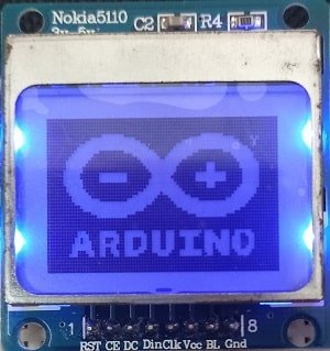
To see the demonstration of the above code, upload the code to Arduino. Before uploading the code, make sure to select the ESP32 board from Tools > Board and also select the correct COM port to which the ESP32 board is connected from Tools > Port.
Once the code is uploaded to ESP32, you will be able to view the monochrome bitmap image as shown below:
Conclusion
In conclusion, we comprehensively looked at the Nokia 5110 LCD display and set it up with the ESP32 board using Arduino IDE. We have learned its introduction, pinout, connection with the development board and some Arduino sketches to get started with the LCD display. The program sketches included displaying simple texts, numbers, ASCII symbols, changing font size, rotating texts, and displaying simple shapes. Additionally, we were also able to display monochrome bitmap images on the LCD screen by following a series of steps.