

Title Block: Need to Know to Improve User Interaction
The Title Block contains the “Meta Data” of the drawing. For example, it tells us the number and name of the drawing.
You can leverage this information with what you need to know to improve the User Interaction.
The title block is normally placed in the bottom right of the drawing frame, and it should contain the following information:
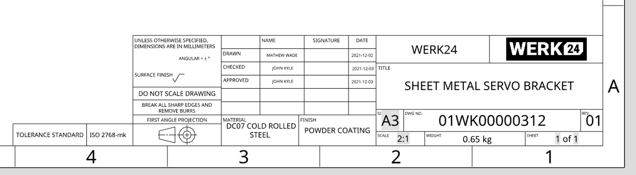
Company or organization name
The name of the company or organization to which the component belongs. You can add the name of the company or business where this technical drawing was created.
Company Logo
The Logo of the company or organization to which the component belongs.
Title of the drawing
The title of the drawing should be concise and to the point. Using the words 'or' or'for' in the drawing title is not recommended.
Drawing number
Drawing number is generally a unique filing identifier. It is the number assigned to the drawing generated for a particular component. It may be unique in relation to the part number. As a rule, each organization has its numbering framework for specialized drawings.
Revision number
Revision Number is the count of current revisions of the part.
When a component is modified, it is recommended to modify the existing engineering drawing to incorporate the changes. Once the changes have been made, the existing drawing is superseded, replaced by the new version. In a Drawing Management System, these kinds of changes are completed within a document workflow and often require engineering review and approval.
During the life of a product, parts that are used for many years, may be revised several times to improve performance or reduce cost. After a drawing change request is made, the drawing is modified. Any change to a drawing after release, shall be recorded in the Revision History Block.
When a drawing is first issued, it is called revision zero or dash (-), and the revision block is empty. As each revision is made to the drawing, an entry is placed in the revision block. This entry will provide the revision number, a summary of the revision, the date of the revision, and approver name.
As the component is modified, and the drawing is updated to reflect the changes, the revision number is increased by one, and the revision number in the revision block is changed to indicate the new revision number. For example, if a Revision 2 drawing is modified, the new drawing showing the latest modifications will have the same drawing number, but its revision level will be increased to 3. The old Revision 2 drawing will be maintained in the filing system for reference.
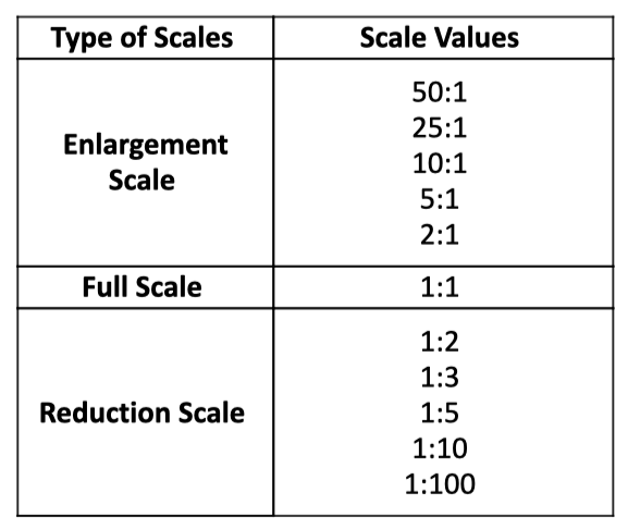
Scale
Drawings may be made actual size, or they may be made smaller or larger than the actual size of the object. A drawing that is twice the actual size of the part would show a scale of 2 = 1 or 2:1. A drawing made half the actual size of a part would be in a scale of 1/2 = 1 or simply 1:2.
Drawing Size or Sheet Size
The size of the form for the original document, e.g. A4, A3. If a technical drawing is drawn in different sizes with respect to the original size, you can understand it from this area.
Projection Method
Either first or third angle, generally shown symbolically (Explained in “Projection Method“ sections)
Signature or Initials
Signature or initials of the draftsman, checker, approving officer, and issuing officer, with the respective dates. This section shows the information about the person performing various actions on the drawing.
Material
Material used for the manufacturing of the part.
Material Standards:
European standards for metallic materials
In the table of European standards for metallic materials, specifications for seamless and welded steel pipes and pipes products, wire and wire products, forgings, sheets, strips and definition of steel products are presented.
ASTM Standard List: Ferro Alloys, Other Materials and Terms and Definitions
ASTM specifications represent a consensus among producers, specifiers, fabricators, and users of steel mill products. ASTM’s designation system for metals consists of a letter (A for ferrous materials) followed by an arbitrary sequentially assigned number. These designations often apply to specific products, for example A548 is applicable to cold-heading quality carbon steel wire for tapping or sheet metal screws.
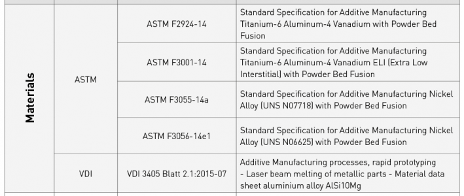
Additive Manufacturing materials
SAE Standards
J1086
J411 Sept97 IR - Carbon and Alloy Steels
J935 Mar96 RP - High Strength Carbon and Alloy Die Drawn Steels
J402 Nov93 S - SAE Numbering System for Wrought or Rolled Steel
J1442 Nov93 RP - Steel, High Strength, Hot Rolled Plates, Bars, and Shapes
J438b Apr70 S - Tool and Die Steels
J1072 Feb77 RP - Sintered Tool Materials
J471 Aug73 S - Sintered Powdered Metal Parts: Ferrous
AISI Standards
The SAE system uses a basic four-digit system to designate the chemical composition of carbon and alloy steels. The first digit (1), of this designation, indicates carbon steel; i.e., carbon steels comprise 1xxx groups in the SAE-AISI system and are subdivided into four categories due to the variance in certain fundamental properties among them.
AMS standards
This group of AMS steel specifications covers carbon and alloy steels, plates for boilers and other pressure vessels, sheets, strips and bars, high-strength low-alloy steels, heat-treatable steels, hot and cold-rolled plates for cold forming. This article also contains standards for various types of steel pipes which specify requirements for high-temperature service, ordinary use and special applications such as fire protection use. Specifications for steel tubes list standard requirements for boiler and superheater tubes, general service tubes, steel tubes in refinery service, heat exchanger and condenser tubes, mechanical tubing and structural tubing. Steel casting specifications call out the standard properties for pressure purposes. The group of standards for cast iron and low alloy steels, cast corrosion and heat resistant steels, and group of standards for wrought corrosion and heat resistant steels and alloys are also presented.
Weight of the part
Total weight of the part with proper units. There are various units that can be used to express the part weight. For example, kilograms, grams, milligrams, etc.
Moreover, there are some weight units based on unit length. For example, kilograms per meter (kg/m), grams per centimeter (gm/cm).
Sheet number for multi-sheet drawings
Individual sheet numbers among the total sheets used to describe a part. If the part drawing contains several sheets, you can find information about the sheet number in this section.
General Tolerances:
Tolerances that define how accurately a part must be made, when the tolerance is not specified for a dimension.
General Tolerance Standards:
ISO 2768:
ISO 2768 and the derived geometrical tolerance requirements are especially applicable to components that are manufactured by using machining or different material removing processes. The ISO 2768 only applies to the following drawings with the subsequent features. it is used when these functions do not have custom tolerance indications individually:
Linear dimensions (external sizes, internal sizes, diameters, distances, chamfer heights, radii)
Angular dimensions
Linear and angular dimensions produced by machining assembled parts.
The ISO 2768:1989 standard was developed by the Technical Committee on Limits and Fits within ISO (ISO/TC3). It consists of two parts: ISO 2768-1 and ISO 2768-2.
Part 1 – General Tolerances for linear and angular dimensions.
Part 2 – Geometrical tolerances for features.
ISO 286
IT grade(s) refer to an internationally accepted code system for tolerances on linear dimensions. Such code systems may be used to produce interchangeable parts. In engineering, the word tolerance refers to a range of allowable dimensions or values. Standard tolerance grades are a group of tolerances for linear sizes characterized by a common identifier. For SI measurements, a system of tolerance grades defined in ISO 286 is frequently used and identified by the letters IT followed by a number specifying how precise the requirements are, relative to the nominal size of a part.
The standard ISO 286 defines the system of tolerances, deviations and fits only for basic sizes up to 3150 mm. However, IT grades can be extrapolated in the following way.
Finish / Surface Finish Method
The treatment or coating that the component is finished to is stated in the title block. There are numerous surface finishing methods. Some of the general methods are stated here.
Ultrasonic Polishing
Magnetic Polishing
Sandblasting
Anodizing
Powder Coating
Electroplating
Polishing
Buff Polishing
Grinding
Lapping
Hot Blackening
Vibratory Finishing
Brushing Metal
FAQs
What is Title Block with incomplete grid lines?
Companies have their unique style in technical drawings. Some of these drawings may have Title Blocks with grid lines that are not fully connected, lines that are missing, or a whole Title Block table with dashed lines. These instances of Title Blocks with incomplete grid lines can lead to misinterpretation by the reader.