

Introduction: Raspberry Pi Pico - Nokia 5110 LCD (Setup + Example Project)


Welcome to this Raspberry Pi Pico tutorial. We are going to look at how to interface the popular Nokia 5110 LCD, to the Pico, to give our projects a great LCD display.
The project uses a library written for the pcd8544 controller in MicroPython. We will look at how to display the onboard temperature sensor on the Pico to the screen, and where you can find other examples.
This Nokia5110 is a basic graphic LCD screen for many applications, and you will often see it being used in DIY projects. There are many resources on using this LCD screen with different microcontrollers and libraries. I have not found many resources regarding the use of this LCD with the Raspberry Pi Pico and I hope this one will help you.
Supplies


Here are the list of all the components and parts needed to build this project. The links to these products are what I found I online, which I have not personally used or affiliated with so use this as reference only.
- Breadboard - AliExpress
- Few jumper wires (Male to Male) -AliExpress
- Nokia 5110 LCD Module - AliExpress
- Raspberry Pi Pico - AliExpress
- Computer device to program Pico with an IDE ( Using Thonny in this example, if you are not sure how to setup Thonny or Micropython go watch this video. )
Step 1: Nokia 5110 Module + Circuit Diagram + Circuit
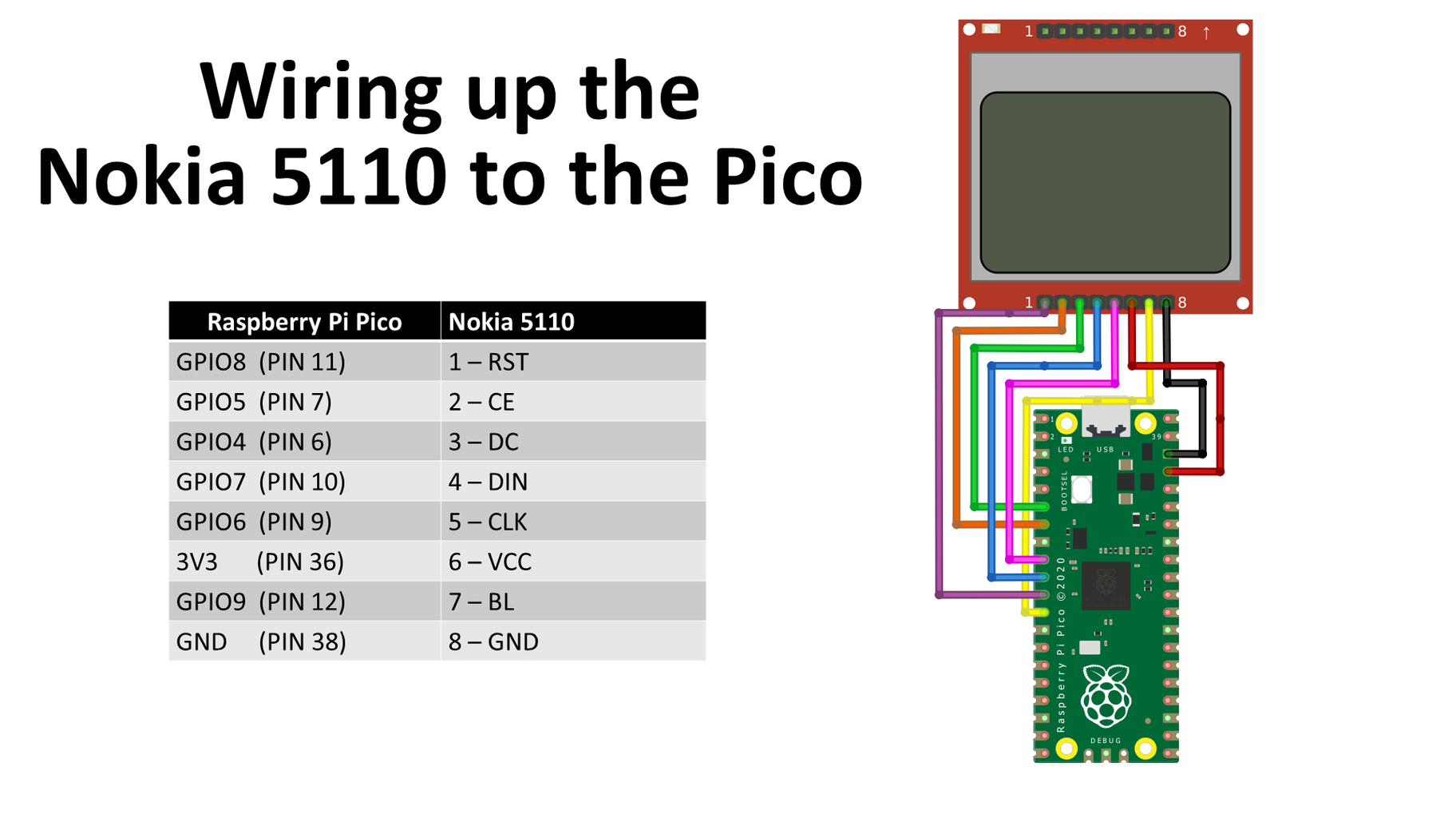


The module has eight pins and interfaces with the Pico SPI communication. The table show each GPIO pin being used with the Physical pin indicated on the Pico and to which Pin it is connected to the Nokia 5110.
I made the connections above, but you might want SPI1 or a different pin to control the Backlight in your personal project.
Make all the necessary connections following the circuit diagram in Step 1. The figure above shows the completed circuit on a breadboard.
Step 2: Coding


In this project we import one library. The library for the pcd8544 controller is written in Micropython which can be download by the following link (Or download below).
Open and copy all the code in the pcd8544_fb.py file (Figure 1).
In Thonny create a new file and paste the code. Save the file to the Pico and make sure to call the filename pcd8544_fb.py.
The code for the temperature example can be found in my github repository by using the following link (Or download below).
Now create a new file and import the library, and from machine import Pin, SPI. This will allow us to have access to the GPIO of the Pico and SPI communication protocols.
import pcd8544_fb
from machine import Pin, SPI
import utime
We need to setup the pins and enable the SPI communication which is done by the following block of code. If you use different pins update the code accordingly. We also set the backlight to be on by assigning it a value of 1.
We create a variable called lcd to initialize our LCD using the library by setting it equal to the variable lcd.
# set up pins
spi = SPI(0)
spi.init(baudrate=2000000, polarity=0, phase=0)
cs = Pin(5)
dc = Pin(4)
rst = Pin(8)

# set bl on/off
back_light = Pin(9, Pin.OUT, value=1)

#initialize lcd
lcd = pcd8544_fb.PCD8544_FB(spi, cs, dc, rst)
The Pico has an onboard temperature sensor. We can read the sensor's analog data, convert it, and display it on our screen. We read the temperature sensor value and create a conversion factor done by the following block of code.
# Setup temperature sensor read value
# on ADC 4 - Onboard temperature sensor
sensor_temp = machine.ADC(4)
conversion_factor = 3.3 / (65535)
In our main loop, we create a variable temperature and set it equal to a function read temp() that will do all the calculations to receive the temperature from the onboard temperature sensor.
while True:
  temperature = read_temp()
  display_temp(temperature)
  lcd.fill(0)
Then display_temp() function, which we will display the temperature on the screen.
read_temp()
In the read_temp function we create a variable reading which will give you an integer number between 0 and 65535, so we have to convert this value to the Celsius degree scale.
The temperature sensor works by delivering a voltage to the ADC4 pin that is proportional to the temperature. From the datasheet, a temperature of 27 degrees Celsius delivers a voltage of 0.706 V. With each additional degree the voltage reduces by 1.721 mV or 0.001721 V. The first step in converting the 16-bit temperature is to convert it back to volts, which is done based on the 3.3 V maximum voltage used by the Pico board.
With this conversion, the variable reading holds a value between 0 and 3.3. We again have to do the second conversion which brings the temperature to the Celsius scale.
Then we just format it to be two decimals, save it in a string, and return that string which is assigned to the variable temperature.
def read_temp():
    reading = sensor_temp.read_u16() * conversion_factor
    temperature = 27 - (reading - 0.706)/0.001721
    formatted_temperature = "{:.2f}".format(temperature)
    string_temperature = str("Temp:" + formatted_temperature)
    print(string_temperature)

    return string_temperature
The variable is then given to the display_temp() function.
Here we use the lcd.text to write any text we want, for the example of the video I wrote my YouTube channel name NerdCave. How this works is the first variable is a string, second the x coordinate, third the Y coordinate, and the last one for text to be visible or not.
We then write the string to our screen and move down the starting y coordinate, clear the screen first and then show the text to the screen. I added a short delay to see the change in temperature in the shell.
def display_temp(string_temperature):
    lcd.text('-NerdCave-', 0, 0, 1)
    lcd.text(string_temperature,0, 12, 1)
    lcd.clear()
    lcd.show()
    utime.sleep(2)
And then finally, we have LCD. fill(0) to erase everything before the screen is updated with a new temperature in our main loop.
while True:
  temperature = read_temp()
  display_temp(temperature)
  lcd.fill(0)
That is how it works in short, if you have any questions ask me.
Attachments

Step 3: Testing + More


There are other great examples you can explore in this github repository, with all the source code. If you make a project using this LCD let me know in the comments would love to see it. I hope you found this project useful.


